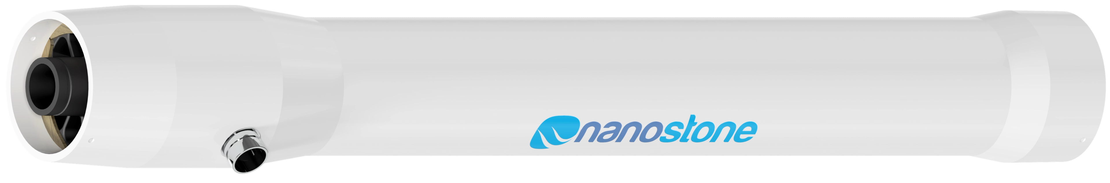
CUF|Flow™ Ceramic Membranes | More Water. Same footprint | Same water. Smaller footprint
CUF|Flow™
More Water. Same Footprint.
Same Water. Smaller Footprint.

When capacity is limited and space is tight, Nanostone CUF|Flow™ offers a smarter way to scale ultrafiltration, expanding output or reducing module count without new construction or costly upgrades.
A smarter way
to scale ultrafiltration
Nanostone CUF|Flow™ is the next-generation ceramic UF module from Acuriant Technologies, Inc. Designed for low-to-moderate solids applications, it expands capacity or reduces footprint without new construction, bringing resilience, cost savings, and sustainability to municipal and industrial water treatment projects.
What’s New
Why CUF|Flow™ changes the game
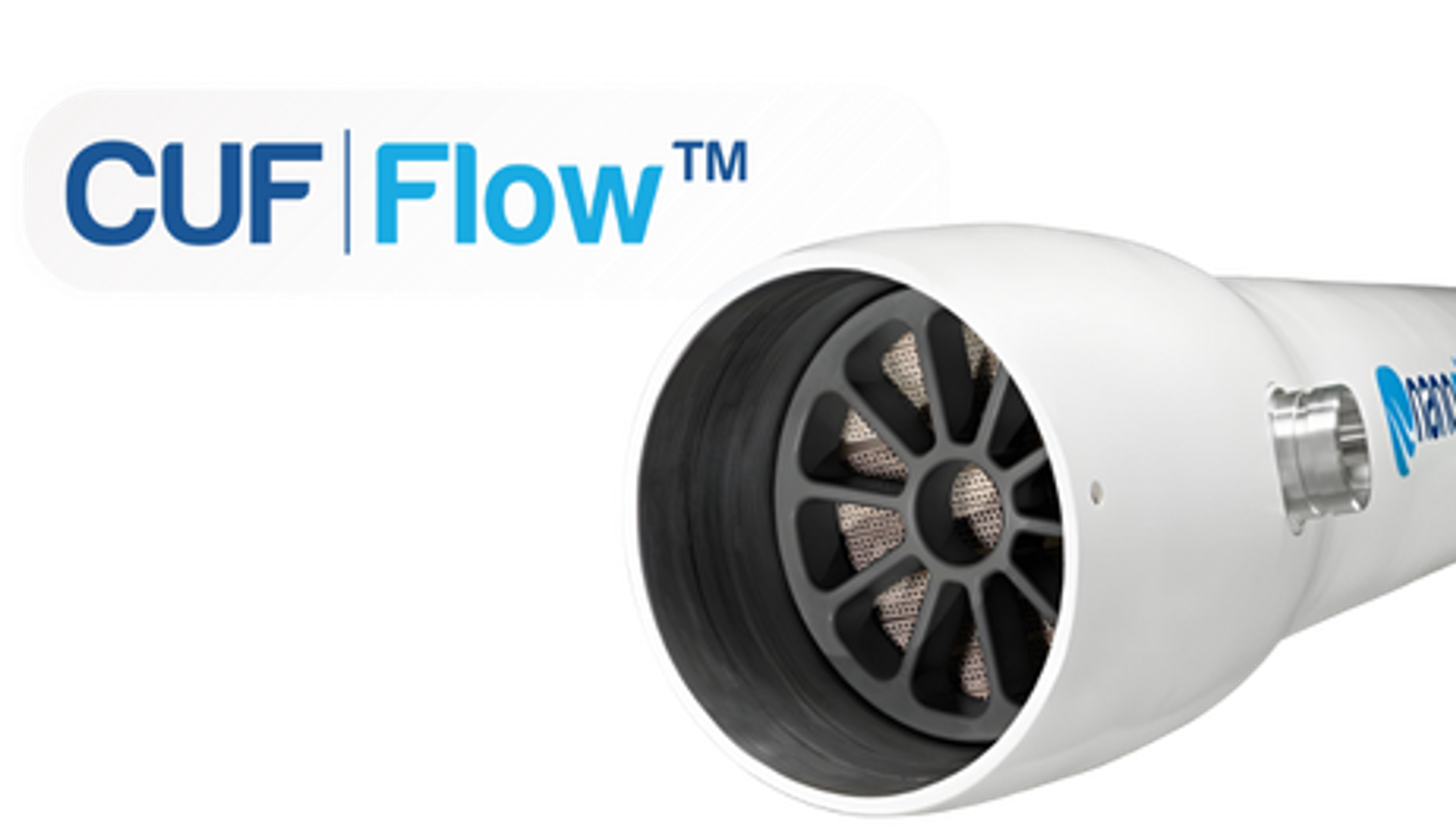
≈40% more surface area (CUF|Flow = 34.0 m² vs CUF|Shield = 24.3 m²) in the same housing.
Installs exactly like CUF|Shield™ (identical housing, ports, piping).
Two deployment approaches:
- Capacity-approach: ≈40% more design flow, no added footprint.
- Efficiency-approach: ≈30% fewer modules for the same output.
Explore how CUF|Flow™ compares to CUF|Shield™ and CUF|ShieldPlus™.

Where CUF|Flow™ Fits Best
- Municipal drinking water (clarified surface water, groundwater)
- Municipal wastewater reuse
- Industrial reuse, cooling-tower makeup, RO pretreatment
- Desalination pretreatment with low-to-moderate fouling feeds
For high-solids or aggressive streams, see CUF|Shield™ and CUF|ShieldPlus™.
Where and How CUF|Flow™ Creates Value:
Three Contexts, Two Approaches
Choose your deployment context:
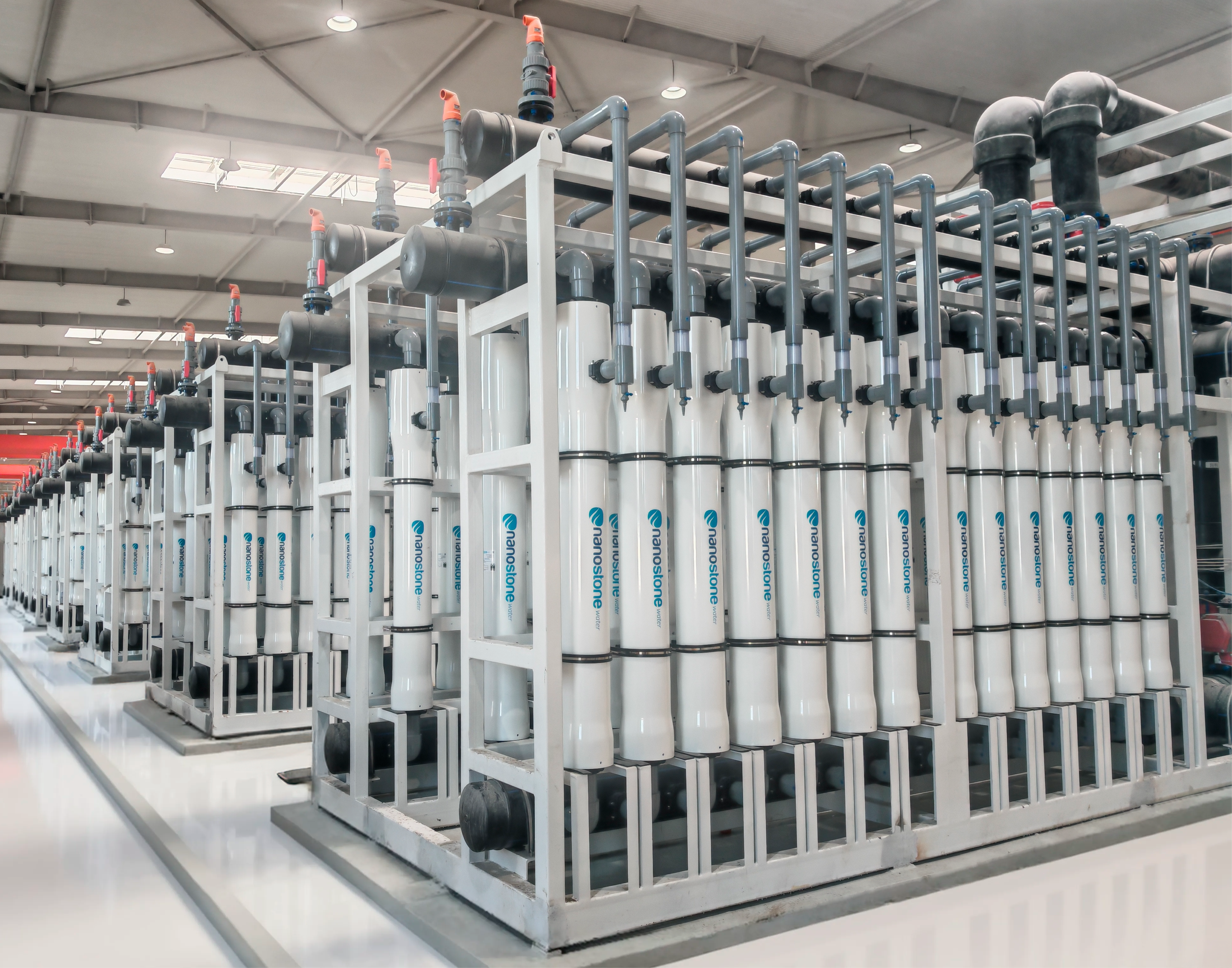
- Existing Nanostone Installations: Swap CUF|Shield™ for CUF|Flow™ to expand capacity or reduce module count with minimal piping changes.
- Competitive Retrofits: Replace polymeric systems with ceramics that last longer and run cleaner.
- New Greenfield Plants: Design compact, cost-effective systems that balance growth, permitting, and sustainability.
Choose your deployment approach:
- Capacity approach: Each module can produce up to ≈40% more design flow at the same flux, supporting capacity expansion without construction.
More Water. Same Footprint - Efficiency approach: Plants can deliver the same water output with ≈30% fewer modules, reducing rack count, installation cost, and lifecycle maintenance.
Same Water. Smaller Footprint.
The table below highlights how these deployment approaches create value across existing Nanostone CUF|Shield plants, competitive retrofits, and new greenfield designs.
Deployment context
Existing plants with Nanostone CUF|Shield (CM-151) modules
Capacity Approach
Drop-in upgrade: swap CUF|Shield for CUF|Flow to increase per-module flow and train output without expanding the rack. Valve-rack and membrane-rack piping, pumps, and tanks may need upsizing to support higher instantaneous flows; limited civil work may be required.
Efficiency Approach
Module consolidation: keep the same water output with ~30% fewer modules. When replacing CUF|Shield, existing membrane-rack and valve-rack piping typically remain in place, reducing installed cost and simplifying O&M.
Deployment context
Existing plants with competitive UF or MMF + UF systems
Capacity Approach
Performance retrofit: replace polymeric/MMF+UF trains to increase output in the same footprint. Expect piping and utilities upsizing (feed and backwash pumps, headers,CIP/BW tanks).
Efficiency Approach
Lifecycle cost reduction: deliver the same output with fewer modules and racks. When replacing polymeric systems, most of the upsizing noted at left applies; the benefit is fewer modules, fewer connections, and lower O&M over time.
Deployment context
New plants (Greenfield projects)
Capacity Approach
Future-ready design: build higher capacity into the same building footprint, potentially deferring expansions. Size utilities and piping for the higher per-module flows from day one.
Efficiency Approach
Compact and cost-efficient: design for fewer modules and smaller membrane racks from the start. Auxiliaries and pretreatment may remain unchanged and should be sized to duty.
Notes:
Capacity approach often requires piping and utility upsizing (feed and backwash pumps, header diameters, CIP/BW tanks) and sometimes limited civil work.
Efficiency approach typically reuses existing piping when replacing CUF|Shield modules; polymeric retrofits generally still need the upsizing outlined under Capacity.
The Economic Case of CUF|Flow™
Redefining the economics of ceramic UF
Redefining the economics of ceramic UF
The increase in packing density fundamentally alters the design math, making long-held assumptions about ceramic membranes, cost per m³, and plant layout no longer valid. This is not just an incremental improvement but a leap that reshapes how capacity, footprint, and cost need to be evaluated. Assumptions based on conventional modules, and the calculations that underpin plant designs and lifecycle costs, no longer hold.
For owners, EPCs, and operators, CUF|Flow™ requires a fresh look at project economics and design choices. The uplift in output density is significant enough to render traditional planning rules-of-thumb obsolete, opening opportunities to achieve capacity expansion or footprint reduction that were not previously possible.
Lower total installed cost
Lower total installed cost
Each CUF|Flow™ module contains ≈40% more membrane surface area in the same housing. This does more than reduce module count. It cascades through the balance of plant, cutting the number of racks, valves, interconnects, instruments, and the structural steel required. The result is a lower Total Installed Cost (TIC), not just lower module CAPEX.
Budget and permitting flexibility
Budget and permitting flexibility
By reducing rack footprint, CUF|Flow™ helps projects fit inside existing layouts and capital envelopes. Municipalities and industrials facing space constraints or budget caps can use CUF|Flow™ to make projects feasible that would otherwise stall or fail to gain approval.
Reduced project risk and shorter schedules
Reduced project risk and shorter schedules
Fewer racks and modules also mean less piping and fewer connection points, which shortens installation time and lowers the chance of site errors. In projects with strict delivery deadlines or liquidated damages for delays, this schedule certainty can carry considerable financial value.
Lifecycle savings that compound over time
Lifecycle savings that compound over time
The efficiency continues after installation. Operators carry fewer spares, need less warehouse space, and spend less time on module maintenance. With fewer modules in service, cleaning frequency and chemical costs can also be reduced. Over a 10-15 year horizon, these savings compound into meaningful OPEX reduction.
The Sustainability Case of CUF|Flow™
Lower embodied carbon from fewer modules
Lower embodied carbon from fewer modules
In the efficiency approach, CUF|Flow™ reduces the number of modules by nearly 30 percent. This cascades into fewer racks, valves, instruments, and pieces of structural steel. In a 500 m³/h plant, this means ≈ 74 fewer modules and six fewer racks. The avoided manufacturing, transport, and installation directly reduce embodied carbon per cubic meter of water treated.
Construction avoidance and infrastructure efficiency
Construction avoidance and infrastructure efficiency
In the capacity approach, CUF|Flow™ expands throughput without expanding footprint. This avoids the embodied carbon of new concrete pads, structural steel, HVAC systems, and auxiliary equipment that would otherwise be required in a plant expansion. For owners and EPCs, the carbon savings from avoiding new construction are often larger than the carbon footprint of the membranes themselves when quantified using standard emission factors.
Lifecycle environmental benefits
Lifecycle environmental benefits
Over the long term, CUF|Flow™ also reduces lifecycle impacts. Fewer modules in service mean fewer replacements over the operating life of the plant, less packaging waste, and reduced logistics emissions from shipping. For operators pursuing multi-year ESG targets, these lifecycle reductions accumulate into meaningful carbon avoidance.
Alignment with ESG and net-zero strategies
Alignment with ESG and net-zero strategies
Both deployment approaches allow avoided emissions to be calculated using standard carbon accounting factors and reported as carbon savings per cubic meter of treated water. This provides utilities, municipalities, and industrial clients with quantifiable contributions toward their ESG disclosures and net-zero strategies. CUF|Flow™ helps transform sustainability goals from aspiration into measurable performance.
CUF|Flow™: More than a larger module.
A new baseline for ceramic UF.
Our experts are ready to help evaluate your site conditions and project goals.
Book Your Discovery Call
Explore the advantages of CUF|Flow™.
The newest Nanostone ceramic UF module delivers ≈40% more membrane area in the same housing, giving you the choice of higher throughput or fewer modules.